SA-5 Saturn I Block II Vehicle Description (small).pdf - Heroicrelics
SA-5 Saturn I Block II Vehicle Description (small).pdf - Heroicrelics
SA-5 Saturn I Block II Vehicle Description (small).pdf - Heroicrelics

Transform your PDFs into Flipbooks and boost your revenue!
Leverage SEO-optimized Flipbooks, powerful backlinks, and multimedia content to professionally showcase your products and significantly increase your reach.
R -P&VE -V<strong>SA</strong> - 63-1 8 1Decembe r 2 6, 1963<strong>SA</strong>-5 <strong>SA</strong>TURN I BLOCK <strong>II</strong> VEHICLE DESCRIPTIONb yASSEMBLY ENGINEERING SECTIONVEHICLE ENGINEERING BRANCHVEHICLE SYSTEMS DIVISIONPROPULSION AND VEHICLE ENGINEERING LABORATORYNational Aeronautics and Space AdministrationMSFC - Form 454 (Revlaed September 1961)
GEORGE C. MARSHALL SPACE FLIGHT CENTERR-P&VE-V<strong>SA</strong>-63-181<strong>SA</strong>- 5 <strong>SA</strong>TURN I BLOCK <strong>II</strong>VEHICLE DESCRIPTIONbyASSEMBLY ENGINEERING SECTIONABSTR ACTThe illustrations and text in this publication briefly describe the<strong>SA</strong>- 5 <strong>Saturn</strong> I <strong>Block</strong> <strong>II</strong> vehicle. The purpose of the manual is to provideinterested NA<strong>SA</strong> and contractor personnel with a summary of thevehicle configuration.
GEORGE C. MARSHALL SPACE FLIGHT CENTERR-P&VE-V<strong>SA</strong>-63-181<strong>SA</strong>-5 <strong>SA</strong> TURN I BLOCK <strong>II</strong>VEHICLE DESCRIPTIONbyEngineering Communications DepartmentChrysler Corporation, Space DivisionHuntsville Ope rationsUnder the Technical Supervision ofAssembly Engineering SectionV e hicle Engineering Branch<strong>Vehicle</strong> Systems DivisionPropulsion and <strong>Vehicle</strong> Engineering Laboratory
TAB LE OF CONTENTSParagraphPageINTRODUCT ION ..... . 1A. GENERAL DESCRIPTION . 3B. S-I STAGE, GENERAL . 3c. S-IV STAGE, GENERAL 19D. INSTRUMENT UNIT . 22E. PAYLOAD ... . . . 24F .PROPELLANT DISPERSION SYSTEM (DESTRUCTSYSTEM) ................... . 24111
LIST OF ILLUSTRATIONSFigureTitlePageFrontispiece .•.. • • •S-I Stage242345678910Tail Unit Assembly.Tail Area, Outboard Engines RemovedTail Area, Complete .Propellant ContainersSpider Beam and Top Tank Area.Movie a nd TV Camera Installation.S-IV StageS-IV Forward InterstagePropellant Dispersion System (Destruct System)7810121518202325Table123LIST OF TABLESTitleS-I Stage Statistical Data.Major Similarities and Differences of Containers .Container IdentificationPage51314iv
INTRODUCTIONThis manual presents a brief descriptive summary of major vehicleassemblies contributing to the <strong>Saturn</strong> I configuration peculiar to S A - 5 , andprovides a c apsule reference guide to the vehicle.The manua l first briefly describes the overall vehicle, then describesthe vehicle stages and major assemblies of each stage. For detailed informationa bout certain assemblies, refer to the <strong>Saturn</strong> I assembly drawings,the <strong>Saturn</strong> <strong>Vehicle</strong> Data Book, the <strong>Saturn</strong> Technical Information Handbook,the <strong>Saturn</strong> <strong>Vehicle</strong> Instrumentation Systems Manual, Douglas AircraftCompany's Technical Support Document DSV - IV - I, <strong>SA</strong>- 5 LOX System (Dwg.No. 10M30012), I N - P&VE- V - 63- 2, <strong>Saturn</strong> I P ropellant Dispersion System,and Sat urn I <strong>Block</strong> <strong>II</strong> Flight Measur ements M anual Volumes I through IV.1
Fl ELD SPLICEINSTRUMENT UNIT1------ 154 INCHESt------lFIELD SPLICESEPARATIONFIELD SPLICE164 FEETS-1 STAGE21 FEET INCHES<strong>SA</strong>-5 VEHICLEC-H61782
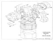
TV CAMERAINSTRUMENTCOMPARTMENT(TYPICAL F-1 & F-2)ANTI-SLOSH BAFFLES(105" OIA LOX TANK)CABLE TRUNKHYDROGENCHILL-DOWNDUCTHEAT SHIELDTURBINEEXHAUSTDUCTC-H 6179FIGURE 1.S-I STAGE4
Table 1.S-1 Stage Statistical DataGross Weight at LiftoffPropellant WeightEngines (8)Thrust per EngineTotal Thrust (sea level)Propellant use per second/per engineTotal Propellant Consumption per secondValves and Control DevicesMeasurt:'!ments during FlightElectrical and Electronic ComponentsElectrical Network Connections(t:!xcluding internal) of abovecomponentsWiring usedStructural FabricationFinal Assembly980, 000 lbs.850, 000 lbs.H-1 Rocketdyne188, 000 lbs.1. 5 million lbs .737 lbs.5, 900 lbs.320740 (approx.)1, 7087 3, 00053 miles27 weeks (approx.)17 weeks (approx.)The base of the S-I stage is the tail section thrust structure assembly.The eight engines attach to the thrust structure aft of the firewall. Theengines are partially enclosed by the tail shrouds and heat shield, and onlythe engine thrust chambers and heat exchangers are visible. Engine thrustis transmitted from the thrust structure through the LOX containers to thespider beam unit assembly.The container section consists of a lOS-inch-diameter center LOX container,four 70-inch-diameter LOX containers, and four 70- inch-diameterfuel containers. The eight 70-inch containers are clustered around the lOSinchcontainer. On <strong>Block</strong> <strong>II</strong> vehicles, the propellant containers have beenlengthened to provide approximately 100, 000 pounds of additional propellants.The combined LOX capacity of the 105-inch LOX container and the four 70-inch LOX containers is approximately 600, 000 pounds. The combined fuelcapacity provided by the four 70-inch fuel containers is approximately250, 000 pounds. The fuel containers are mounted to the spider beam unitassembly with floating attachments to allow for LOX container shrinkagewhen the booster is loaded with liquid oxygen. Two 20-cubic-foot capacity,high-pressure GNz spheres are mounted in the forward sections of fuel containersF- 3 and F-4. Instrument compartments are located in the forwardsections of fuel containers F-1 and F-2.The spider beam forms the forward structure of the stage and serves toanchor the forward end of the propellant containers. Seal plates cover theforward side of the spider beam. A LOX/SOX (liquid oxygen/ solid oxygen)5
disposal syste m, installe d above the seal plates, is used to purge the S-IVinte r sta ge area during S-IV engine chilldown.A c a m e ra system, consisting of eight movie cameras and one TV camera, is installed on the spider beam to observe stage separation and propellantsloshing during flight.1. Tail Area. Installation of the water quench and barrel heatersyste m, engine purge system, LOX and fuel wraparound suction lines, lowerLOX r e ple nishing line, and fire detection system, transforms the structuralt a il s e ction assembly 30M01000 into the tail unit assembly 10Ml0013. Toutiliz e optimum accessibility, these installations (Fig. 2) are normally performedbefore the clustering operation.The boattail conditioning and water quench systems 10Ml0162 areperforated pipes routed from a quick-disconnect coupling at the heat shieldup the shroud and along the thrust outriggers at fins I, <strong>II</strong>, Ill, and IV to thecenter barrel. This is a threefold system: first, it provides the necessarywater quench capability for firings; second, it provides a means to purge thetail area by ground source; and third, it provides the necessary ducting forground heating of the tail area.The engine purge system provides for the routing of engine purgelines from the two umbilical service plates on the shroud to the purge manifoldin the c e nter barrel assembly. Lines extend from the manifold throughthe firewall to each of the engines. E ach engine purge system consists of:LOX pump seal purge and gearbox pressurization, LOX dome purge, gasgenerator LOX injector manifold purge, and thrust chamber fuel injectormanifold purge. The LOX pump seal purge and gearbox pressurization obtainsGNz from the control pressure spheres. The rest of the purge systemsobtain GNz from the ground control source.The 1. 5-inch-diameter GOX lines from the GOX manifold to the outboardengines are prefitted for installation after the engines are installed.The mechanical components of the fire detection system are installed, andthe inflight heat shield panels and star assembly are prefitted. R-TESTconfiguration panels are used for static test. The inflight panels are reinstalledduring poststatic and preparation for shipment operations .The component installations in the aft skirts of all the LOX containerunit assemblies are almost the same for each container (Fig. 3) . Twosuction line ball rotor LOX shutoff valves (prevalves) are installed along withthe actuating pressure tubing, and various tubing assemblies used for pre s sure pickup, control, etc. The LOX fill and drain valve and nozzle are installedon the sump of container L-4.6
GOX CONTROLVALVEWRAPAROUND SUCTION LINESUMBILICALSERVI CE PLATEFIRE DETECTION(ME CHAN I CAL)LOWER LOXREPLENISH LINEWATER QUENCH ANDBARREL HEATERSYSTEM (4)C-H 6180FIGURE 2.TAIL UNIT ASSEMBLY7
LOX INTERCONNECT LINELOX PREVALVEINBOARD ENGINE (4)FLAME SHIELD AND ACCESS CHUTEFLAME CURTAINSINBOARD ENGINETURBINE EXHAUSTHEAT EXCHANGERC-H 618~FIGURE 3.TAIL AREA, OUTBOARD ENGINES REMOVED8
The aft skirt of fuel container F- 3 contains the control pres sureGN2 storage spheres with the associated regul a tor s, control valves, andconnecting lines. The control pressure system supplies GN2 pressure tooperat e the electrically-controlled pres sure-ope rated LOX replenishingvalve, LOX vent valves, and LOX and fuel prevalves. The system suppliespressure for pressurizing t h e turbopump gearboxes, purging the LOX seals,and purgi ng the calorimeters.M easurement racks and distributors a r e located in the aft skirts ofall fuel containers. Some of the measuring r acks and electrical d istributorsare shown in figur e 3. For additional information refer to the <strong>Saturn</strong> I<strong>Block</strong> <strong>II</strong> Flight Measurements Manual.Figure 3 shows the LOX and fuel interconnect lines and sucti onlines . E ach outer container supplies one inboard and one outboard engine .The LOX containers are int erconnected through the sump of the 10 5-inchLOX container unit. The LOX r eplenishing syst em is routed from the heatshield to the sump of LOX container L-4.The four inboard engines are rigidly mounted to the thrust structureassembly in a squ are pattern around the centerline of the vehicle. The enginesare cant ed outward at a slight angle . A flame shield and access chuteforms a heat barrier b e tween each of the inboard engines . Additional enginecompartment t emperature control is provided b y the heat shield and the flexibleflame curtains . The inboard engines are exhausted through the inboardengine turbine exha ust system and heat e xcha nger . GOX for pressurizing t heLOX tanks is obtained b y routing LOX through the heat e xchanger a nd convertingit to gaseous oxygen. The gaseous oxygen is routed through a 3 - inch GOXmanifold to a GOX flow-control valve and then through the center LOX tankto the LOX pressurization manifold (GOX distribution system).The outboard engines (Fig. 4 ) are gimbal- mounted to provide amovement of plus or minus 8 degrees in a square pattern. Engine gimbalingis accomplished through two actuators operating in a close d hydraulic system. Gim b aling action is initiated by electrical signal from the guidancesystem through an electro-hydraulic servo valve o n each actuator .Flexible purge and propellant bubbling lines to the engine from thefirewall permit engine gimbaling. The final length of 1. 5-inch GOX line tothe outboard engine is flexible. The turbine e xhaust system is a componentpart of the outboard engine, a nd aspirates through a port on the periphery ofthe engine nozzl e . This type of setup for the exhaust system conserves spaceand permits engine gimbaling. The flexible flame curtains around the engines,while preventing excessive engine compartment t emperatures, allowfreedom of movement for the engines .9
HYDROGEN VENT FAIRING (3)LOX FILL AND DRAIN NOZZLEOUTBOARD ENGINETURBINE EXHAUSTOUTBOARD ENGINEFLAME CURTAINACCESS CHUTE COVERENGINE SKIRT (4)INBOARD ENGINE TURBINEEXHAUST FAIRING (4)C-H6185FIGURE 4.TAIL AREA, COMPLETE10
Four l a rge fins, four stub fins, four inboard e ngine turbine exhaustfairings, three hydroge n vent fairings, eight air scoop skins, and four e ngineskirts a r e ins t alle d on the tail of the S- I stage . Each of the e ight fins has astrain g a g e installation for measure m e nt of stresses during flight. Threeof the stub fins (l0Ml0025) have hydrogen vent installations. The hydrogenvent installa tion, toge the r with the hydroge n vent fairings, serve to aspirateand route awa y from the vehicle vented hydrogen from the S-IV stage . Theturbine exhaust fairings aspirate the exhaust gases from the inboard engines. The a irscoops and e ngine skirts direct the flow of air around the tailsection to control tail heating and aerodynamic loading on the engines .At the forward end of the tail unit 60-degree fairing assemblies providean aerodynamic seal between the propellant container assembly and thetail unit assembly.2. Propellant Containers. The container area (Fig. 5) encompasses the four fuel tanks, the five LOX tanks, and pertinent auxiliary cornponents.The r e are more similarities than differences between the individualcontainers. For a summation of similar and different characteristics, r e f e rto table 2 and figur e 5.a. The center LOX container unit assembly l0Ml0130 is 105inches in diameter and 749. 679 inches long. In addition to the componentsliste d in table 2, the c e nter tank has a sump and fuel interconne ct manifoldlocate d in the a ft skirt.Afte r the auxiliary components (including connecting hardware,tubing, and wiring) are installed in the forward and aft skirts and on theskin, the center LOX container unit assembly becomes the lOS- inch- diameterLOX container unit assembly 10Ml0014. For additional information,refer to LOX container unit assembly drawing 10Ml0014.b. The 70-inch LOX containers are 747. 43 inches long and 70inches in diameter. After installation of the auxiliary components, eachcontainer weighs approximately 3, 900 to 4, 100 pounds. A typical internalarrangement of these LOX containers is shown in figure 5.11
HELl UM SLOSHMEASURING TUBESCABLE CONDUITANTI SLOSHBAFFLE<strong>SA</strong>NTI SLOSHBAFFLESOESCRETELEVEL SENSORGOX LINECONTINUOUSLEVEL SENSORc.H 6236-1FIGURE 5.PROPELLANT CONTAINERS12
Table 3.Container IdentificationContainer Container Unit Assembly Container UnitNun>be r (Internal Arrangement) Assembly (AfterComponent Installation)LOX Drawing No. Drawing No.-- L - 105 10Ml 0 1 30 10Ml 0014L-1 10Ml 0131 10Ml 0005L-2 l OM l O 132 10Ml0006L - 3 10Ml0133 10Ml0007L - 4 10Ml0134 10Ml0008F uel- F - 1 10Ml0135 10Ml0009F - 2 10Ml0136 10Ml 0010F - 3 10Ml0137 lOMlOOllF - 4 10Ml0138 10Ml0012c. The 70- inch-diameter fuel container unit assemblies are743.804 inches long. Table 3 identifies the containers, the internal arrangementdrawings, and the containers after component installation. The internalarrangement of the fuel containers is similar for all containers (Fig. 5) ;however, there are some differences . See table 2. The most obvious differencebetween the fuel containers is the forward bulkheads of containersF - 1 and F-2 that form instrumentation compartments number 13 and 12respectively. Feed through adapters for the fuel pressurization system arealso installed on the forward bulkheads.The electrical cables for valve control, measurements, guidancecontrol, and other instrumentation are routed along the external skinsof the fuel containers and covered with conduit covers. For detailed informationon all containers, refer to the drawings listed in table 3 .3 . Spider Beam Area. The spider beam unit assembly (Fig. 6),while structurally supporting the S - I stage forward end, adapts the S - I stageto the S-IV aft interstage and transmits thrust to the S - IV stage. The assemblyalso provides mounting for the retro rockets, film and TV cameras,the LOX/SOX disposal system, five sets of high pres sure pneumatic triplexspheres, various measuring components, and control and measuring tubing.Seal plates installed on the forward side of the spider beam protect the S - Istage from the blast of the S - IV engines during S - IV stage ignition. Theseplates also form the aft seal of the S - IV aft interstage area, and provide anenvironmentally controlled compartment. Forty- five degree shrouds extendfrom the cross beams of the spider beam to provide streamlining of the for -14
LOX/ SOX DISPO<strong>SA</strong>LDISPER<strong>SA</strong>L MAN I FOLD (6)SPIDER BEAM FAIRI NG (4)He TRIPLEX SPHERES20 CUBIC FOOT SPHEREINSTRUMENTCOMPARTMENTNUMBER 12CYLINDRICAL FAIRINGGN2 TRIPLEX SPHERESC-H 6187-1FIGURE 6.SPIDER BEAM AND TOP TANK AREA15
ward end of the stage. Additional aerodynamic improvement is provided bya 6-inch cylindrical fairing attached to the shrouds and e xte nding over thetank top area. Also, there are aerodynamic improvement fairings at theends of the radial beams and over the r e tro rocket brackets a nd w e ldm e nts .Four ::;olid propellant r etro rockets produce the r e tarding forc e onthe S-1 stage to prevent S-1/S- IV interaction during separation. Each retrorocket de,·elops an average of 37 , 000 pounds of thrust during burning time .The r etro rocket::; ignite during separation 16 to 31 milliseconds after thee xplo sive bolt::;, which secure the S-IV stage to the S-I, are fired . A highvoltage power ::;upply furnishes power to fire four e xploding bridge wire(EB \V) igniter::; in the base of the r e tro rockets . The EBW igniter assemblieS'ignite the solid propellant in the r e tro rocke t s . For more r etro rocket information,r efe r to the <strong>Saturn</strong> <strong>SA</strong>- 5 <strong>Vehicle</strong> Data Book and the <strong>SA</strong>- 5 <strong>Saturn</strong>Tec hnical Information Handbook.The LOX/SOX disposal system consists of four triplex sphere assemblies,a plenum chamber and manifold assembly, solenoid valve s, sixdis per sal manifold assemblies, connecting line s, temperature gages, andassociated tubing and mounting hardware. This system is supplemented byr esidua l GNz from the 20- cubic-foot sphere s. Each dispersal manifold, oneper RL-lOA-3 e ngine, has a line of spray holes drilled around its inner circumferenceso that each ring area becomes saturated by the GNz suppliedfrom the triple x spheres. This gasifies the LOX from the S-IV engines toprevent the formation of solid oxygen (SOX) during the LOX chilldown b eforeS-I/S-IV stage separation.The LOX pre ssurizing and vent system (Fig. 6) is inte rconnectedthrough the pressurization manifold in the forward end of the c ent e r LOXcontaine r. Pre launch pressurization is accomplished by using helium froma ground source . Inflight pre ssurization is maintained by GOX obtained bypassing LOX through the heat exchangers in the engin e turbine exhaust syste ms. The GOX flows into a common manifold, through a flow r e gulatorvalve , and into the c e nter LOX containe r . The remaining LOX containersr eceive GOX from the upper interconnect lines (GOX distribution system)associated with the c e nter LOX container. GOX pressure is bled off by one7-inch and two 4-inch vent lines to the outside during prelaunch operations .For more information on the LOX pressurization and vent system, refer tothe <strong>SA</strong>-5 LOX System, drawing 10M30012.The fuel pressurization manifold interconnects the fuel containersat the forward e nds. Inflight pressurizing GNz is supplied by the two 20-cubic -foot spheres located in the forward skirts of containers F- 3 and F-4.Two fuel vent valves are located in the pressurization manifold in containersF - 3 and F-4 respectively.16
The S-I stage power supply, recording equipment, telemetry equipment,flight sequencing e quipment, s ignal transmitting and receiving equipment,TV t r ansmitting equipment, measuring equipm ent, vehicle control,and other instrumentation and electrical equipment are mounted in instrume ntation compartments 12 and 13 located in the forward skirts of fuel containers F-2 and F-1 respectively. The instrumentation assemblies are firstprefitted in an assembly fixture before they are installed in the vehicle. Formore detailed information, refer to drawings lOM20003 and 10M20004, the<strong>SA</strong>-5 <strong>Saturn</strong> <strong>Vehicle</strong> Data Book, the <strong>Saturn</strong> I <strong>Block</strong> <strong>II</strong> Flight MeasurementsManual and <strong>Saturn</strong> I <strong>Block</strong> <strong>II</strong> <strong>Saturn</strong> Instrumentation Systems <strong>Description</strong>.The instrumentation compartments are cooled during countdown through acooling system that obtains conditioned air and purges GN2 from the environmentalconditioning system of the launch support equipment. Instrumentation,command, TV, and telemetry antennas are ins tailed on panels locatedat the forward end of the stage along fin lines I, <strong>II</strong>, <strong>II</strong>I, and IV.One set of triplex spheres supplies helium for purging the threehydrogen v e nt lines. The camera lenses viewing the insides of LOX containerL-3 and the center LOX container are helium purged by a separatebottle mounted on the side of the !-beam.The helium slosh measuring system measures the amount of inflightsloshing occurring in the center LOX container , LOX container L-2 and fuelcontainer F-4. Supply helium is contained in the sphere located in the forwardskirt of LOX container L-2. For more detailed information, refer tothe <strong>SA</strong>-5 <strong>Saturn</strong> <strong>Vehicle</strong> Data Book.An optical instrumentation system consisting of four direct-viewingcolor movie cameras, four indirect- viewing movie cameras (three color andone black and white), four fiber optics bundles, and a TV camera are mountedon the spider beam at fin lines I, <strong>II</strong>, <strong>II</strong>I, and IV (Fig. 7). One camera witha wide-angle lens and one camera using fiber optics is located at each position.The TV camera is installed on the outer periphery of the spider beamat fin line <strong>II</strong>I. Two camera lights, two strobe lights, and two incandescentlights provide proper illumination for the film and TV cameras.The film cameras are housed in hermetically sealed capsules designedto withstand the rigors of powered flight, ejection, re-e ntry, impact,and salt water immersion. The capsules are installed in camera pod assembliesthat are canted outward and act as ejection tubes to eject the camerasclear of the vehicle. GN2 for the camer a ejection system is obtainedfrom the GN2 manifold to the bottle mounted on the I - b eam for the camerasystem. Camera ejection is sequenced to occur 25 seconds after S-1/S-IVstage separation.17
FILM CAMERAINDIRECT VIEWING(4 PLACES);\\ \;: ~\ ~' \\,I .,\CAMERA LENS ,\' j:STROBE LIGHT(2 PLACES)CAMERA LENSCAMERA LENSC<strong>SA</strong> 2180FIGURE 7.MOVIE AND TV CAMERA INSTALLATION18
The direct-vie wing cameras with wide-angle lens e s film r e trorocket and ullage rocket firing, S-IV stage coasting, and firing of the S-IVstage engines. Two of the indirect-viewing cameras film S - IV stage e nginechilldown and S-l/S-IV stage separation. The remaining two cameras filmLOX sloshing in the center LOX container and LOX container L-3. The TVcamera viewing forward provides real-time coverage of the S-IV e nginecompa rtme nt. The TV came ra monitors ullage rocket tgnition, S-l/S-IVseparation, ignition and firing of S-IV engines after separation, motion picturecapsule ejection and booster tumbling rate . On the <strong>SA</strong>-5 vehicle, realtimecoverage begins before liftoff and continues until impact of the S-Istage. For det a iled information , refer to drawings 10Ml0003, 10M l001 6,the <strong>SA</strong>-5 <strong>Saturn</strong> <strong>Vehicle</strong> Data Book, and <strong>Saturn</strong> Instrumentation Systems<strong>SA</strong>-5.C. S - IV STAGE, GENERALThe S - IV stage (Fig. 8) is a self- supporting structure designed forutilization as the second stage of the <strong>Saturn</strong> I vehicle . The stage, includingthe forward and aft interstage a ssemblies, is 41 feet 5 inches long a nd 18feet 4 inches in diameter through the cente r cylindrical portion.Basically, the stage is a two- section tank structure to which the forwardinterstage assembly, aft skirt assembly, aft interstage assembly, and enginethrust structure are attached. An insulated common bulkhead divides the tankstructure into a forward liquid hydrogen ( LHz) tank and an aft LOX tank. Theinternal surfaces of the tank cylinders feature a milled waffle surface pattern.Access to the interior of the LHz tank is provided through a 28 - inch diametermanhole. Access to the interior of the LOX tank is provided through a detachablesump. A ring- type baffle is installed in the LOX tank to minimizes loshing. An external tunnel extending from the forward interstage a ssemblyto the aft skirt assembly houses various interstage tubing and cables, tubingand fittings from the ambient helium spheres mounted in the forward interstage,and lines from the cold helium spheres mounted inside the LHz tank.1. Tail Area. The engine thrust structur e (Fig. 8) is a truncate dcone of r e inforced skin and stringer construction. The large e nd of the coneis attache d to the aft dome of the LOX tank. The six engines, e ngine hyd raulie-actuatingcomponents, an ambient helium sphere, a control pre ssurehelium sphere , a helium heater assembly, and a h eat shield are mounte d onthe thrust structure. The heat shield provides protection for compone ntsfrom flame and the rmal effe cts from the engines. The ambie nt h e liumsphere supplies helium for LHz prepressurization and for sustaining LHztank pressure during engine chilldown . The control pressure s phe r e s uppliesambient h elium at 3, 000 psig for pneumatic operation of valves tn the LHzand LOX s yste ms, and supplies constant purge for the e ngine g earboxes a ndthe propellant utilization ass e mblies.19
ACCESS DOORTELEMETRY ANTENNA (4)COMMAND DESTRUCT ANTENNA (4)FORWARDINTERSTAGECOLD HELIUM SPHERE (3)CYLINDRICAL LH2 TANKCOMMON BULKHEADULLAGE ROCKET (4)AFT BULKHEADTHRUST STRUCTUREHEAT SHIELDHYDROGENVENTSTACK (3)BLOWOUTPANEL (8)C-H 618920FIGURE 8.S-IV STAGE
Components of the e lectrical power system, the flight control system,and part of the t e lemetry system a r e a lso mounted in the thrust structure.For more detailed information about the e l ectrical and instrumentation systerns,r e fer to Douglas drawings 1A00541-503, 1A01560-l, 1A38355, and787l409.The aft interstage assembly (Fig. 8), located between the S - I stage sealplate assembly and the S-1V a ft skirt assembly, consists of eight mechanicallyjoined a l urni num hone ycomb panels that provide aerodynamic enclosurefor t he a ft end of t he S - IV stage and the LOX/SOX disposal system. Eachpand has a triangular blowout panel for venting LOX/SOX or GOX duringthe LOX chilldown pe riod b e fore S-1/S-1V stage separation and S-1V stageengine igmt10n. The blowout panels a r e j e ttisoned by the force of e xplodingdetona ting cord prior to S - 1V e ngine chilldown. All of the panels may beused as access doors during ground operations . Three e xternal hydrogenvent stacks, attache d to th e inte rstage , dispose of gaseous hydrogen duringchilldown ope rations. The a ft end of the inte rstage bolts to the S-1 stage,and the forward end connects to the aft skirt at the separation plane withfrangible nut and bolt assemblies.The aft skirt assembly (Fig. 8) is a structure of eight mechanicallyjoined aluminum honeycomb panels including an umbilical panel with an airconditioningmanifold opening. The manifold is formed by enclosing theforward a r ea between the aft skirt assembly and the tank structure with aflexible p e rforated membrane. Warm air or GN2 distributed into the aftinte r stage by the manifold maintains proper operating temperatures or areapurge during ground operations. Additional ducts from the manifold conditionthe area betw een the LOX tank and the thrust structure. Conditionedair or GN2 is v e nte d through spring-loaded v ents located in the blowoutpanels at fin line s <strong>II</strong> and IV. Four ullage rockets and their fairings are locatedon the aft skirt, one at each fin line . Ullage rocket firing is the firststep in the separation sequence . The ullage rockets impart forward accele rationwhen fired; this forc e s ettles the fuel to provide a positive turbopumphe ad and aids S-1/S- IV stage separation. The skirt has openings in the skinto accommodat e the three chilldown duct elbows. The aft end of the skirtaccommodates the frangible nut and bolt installations for stage separation.2. Propellant Containers. The LH2 container formed by the forwar d e nd of the tank structure and the forward side of the common bulkheadhas a capacity of 4, 274 cubic feet. Inside surfaces of the LH2 container have3/4 -inch polyure thane foam bonded to the walls. Glass cloth, 0. 10-inchthick, coated with a polyurethane sealant, cove rs the foam . Aroun d pipesand fittings, end grain balsa wood replaces the foam. Mounted inside thetank are fuel mass, t emperature , and liquid level sensors for propellantutilization ope ration and ground monitoring display. Three cold heliumspheres are installed in the container to supply h e lium for inflight LOX tankpressurization. The cold h e lium is expanded by passing it through the helium2 1
heater (Fig. 8). The container accommodates six LHz suction lines (one foreach engine) . Anti vortex screens, mounted on the LH2 bulkhead at eachsuction line outlet, pre vent turbulence and cavitation in the suction lines.Vent and relief valves a r e installed in the forward end of the container. LH2fill, drain, and replenishing are accomplished through one fill and drainvalve located on the bottom of the containers.The LOX container formed by the aft end of the tank structure andtht! aft side of the common bulkhead has a capacity of 1, 262 cubic feet. Thesix suction lines attach to the sump of the LOX container. One anti vortexscreen is n1ounted in the sump. Temperature and mass sensors a re mountedin tht! containe r for propellant utilization operation.3. Forward Inter stage Assembly. The forward inter stage assembly(Fig. 9) is a truncated cone formed of eight mechanically joined aluminumhoneycomb panels and serves to adapt the instrument unit to the S - IV stage .Although the instrument unit and payload will not separate from the S-IVstage during the <strong>SA</strong>- 5 flight, provisions are made in the interstage assemblyfor installing two retro rockets, one each at fin lines <strong>II</strong> and IV. Four telemetryantennas, four command- destruct antennas, and the hydrogen vent couplingare mounted on the external skin. An access door on the exterior skinpermits access to equipment mounted on the interior interstage wall. Tenbackup helium pressurization spheres, mounted on the interstage interiorwall, provide LOX tank pressurization if failure of the primary cold heliumpressurization system occurs. Telemetry equipment and the command destructsystem firing units, safety and arming devices are mounted on anequipment rack on the interior wall.D. INSTRUMENT UNITThe instrument unit on <strong>SA</strong>- 5 contains four horizontal cylindrical compartmentsand a central vertical cylinder. Compartment I carries an activeST-90S guidance package which provides inertial guidance systems controlfor the vehicle. The ST-90S maintains programing through a magnetic tapeactuator. Compartment <strong>II</strong> holds an ST -124 passenger guidance package,which is a digital computer guidance system, and the gyro stabilization electronicbox. Compartment <strong>II</strong>I contains telemetry equipment to transmit signalsfor approximately 335 measurements of pressure, temperature, strain, vibration,flight path, and other data from within the instrument unit. Installedin compartment IV is the AZU<strong>SA</strong> transponder and the power supplies for theinstrument unit and other components throughout the vehicle. The guidancesignal processors, flight control computers and sequencers, power distributors,the UDOP transponder, and MISTRAM transponder are contained inthe center cylinder (compartment V).22
i-+-----------152.51N.------------iBACKUP PRESSURIZATIONSPHERE (10)HYDROGENTANK VENTCOUPLINGTUNNELACCESSTELEMETRYANTENNA(4 PLACES )22.5°COMMAND DESTRUCTANTENNA (4 PLACES)PANEL SPLICE(8 PLACES)C<strong>SA</strong> 4004FIGURE 9.S-IV FORWARD INTERSTAGE23
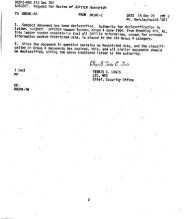
Th1..' five cotnpa rtme nts a r e air conditione d and pre ssurize d by GNz fromtwo high-pressure sphe r e s mounte d on the lowe r oute r wall of the c e ntralcylinder. The c ooling syste m maintains a stable acce ptable tempe raturewithin thl..! in::>trurne nt unit during v e hicle pre flight a nd flight .The instrume nt unit b e gins to function before liftoff in orde r to s e que ncethe S-1 e ngine sta rt a nd control. Programing and flight control from the unitcontinue s throughout the ope r a tional flight of the S-I stage. The instrume ntunit initia te s s t age s epa ration sequen cing at the termination of the S-I stageope r a tion as w e ll a s engine start for the S-IV stage . At the time of separation,control i s switched from the S-I stage to the S - IV stage by the i n strume nt u nit. Ins trume nt programing and flight control of the S-IV continuesdurin g the ope r a tion of the S-IV engines . Three telemetering sets are alsocontrolled b y the instrument unit.For d e taile d information on the instrume nt unit, refe r to drawingl OM20000, the <strong>SA</strong>- 5 <strong>Saturn</strong> <strong>Vehicle</strong> Data Book, and the <strong>SA</strong>-5 <strong>Saturn</strong> V e hicleT e chnical Information Handbook.E .PAYLOADThe payload assembly for <strong>SA</strong>- 5 consists of a modified Jupiter nose coneand aft unit. The payload mates to the instrument by means of the payloadadapte r asse mbly. The adapte r assembly has 16, 800 pounds of sand ballastto simulate the w e ight of the Apollo spacecraft. Payload instrumentation includes four angle of attack transducers, Q-ball transducer and minitracktracking syste m . The payload is 37 . 5 feet long, 154 inches in diameter andis d e signed to burn up at re-entry. For more detailed information about thepayload, r e fe r to drawings 10M20002, 30M05199, 10485600 and 8923600.F. PROPELLANT DISPERSION SYSTEM (DESTRUCT SYSTEM)The <strong>Saturn</strong> I <strong>Block</strong> <strong>II</strong> propellant dispersion system (Fig . 10) provides ameans of terminating vehicle flight by command signals from the ground tothe vehicle receiving antennas. Each stage has a separate and independentdestruct system consisting of the following major components:a. Four receiving antennas to receive commands from the ground.b .c .Two separate and independent command systems to demodulate,d e code, and transmit the signals from the ground.An independent exploding bridgewire (EB W) firing unit linke d toe ach command system, to provide an electrical charge to initiatedetonation.24
<strong>II</strong>/, )I ----/ \I \I \I \~ J1',/ <strong>II</strong> -------- IJI\~~ ..... -- //)--... --- --_../ <strong>II</strong> -~---- <strong>II</strong> <strong>II</strong><strong>II</strong><strong>II</strong>I\<strong>II</strong><strong>II</strong><strong>II</strong><strong>II</strong><strong>II</strong><strong>II</strong><strong>II</strong><strong>II</strong><strong>II</strong><strong>II</strong><strong>II</strong><strong>II</strong><strong>II</strong><strong>II</strong><strong>II</strong>r-----1 :I I ll<strong>II</strong> _... 1/"l I Il. ( )1 A 1'-.J._ I..... "' / '-1" n '\ " t....I 1' , I I ' / 1 1 ~ '-../ ) '-1 Y L - ~ l- _.... I '~I I I ~--- I I 1~)/ : I~ : Ih J I i1 ">- -... <strong>II</strong>I ,{_ 1'' -1' / '--..j/1 / --- lf-1I I / \ \).J /L .V'\_;_ -;;JC- H 6191FIGURE 10. PROPELLANT DISPERSION SYSTEM (DESTRUCT SYSTEM}25
d. A separate high-voltage detonator linked to each EB W firingunit, to initiate detonation of the e xplosives.e .A safety and arming device to complete or interrupt theexplosive train.f. Explosives.The destruct system e xplosives for these vehicles consist of 50 and 60grains per foot (gpf) pentaerythritetetranitrate (PE TN) Primacord, nine 100gpf PETN flexible linear - shaped charges in the S-I stage, and 100 gpfCyclotrimethylene Trinitramine (RDX) linear-shaped charge in the S-IV stage.The Primacord propagates the e xplosion to the shaped charges, which cutthe propellant containers, thereby dis per sing and igniting the propellants andlimiting the explosion to a fraction of its possible intensity. The flexiblelinear- shaped charges (FLSC) o n t he S-I stage are insert ed into conduits extendingalmost the full length down the outside of the 70 - inch diameter propellantcontainers and approximately 20 feet down the outside of the 105-inch-diameter center LOX container . The linear - shaped charge (LSC) isinstalle d down the outside of the LH2 container and around the bottom LOXcontainer bulkhead of the S-IV stage.D e tailed information on the propellant dispersion system is found inIN-P&VE-V-63- 2, the <strong>Saturn</strong> I <strong>Block</strong> <strong>II</strong> Propellant Dispersion System anddrawings 10Mll318-l and 10Mll319-l.26
APPROVAL<strong>SA</strong> TURN I BLOCK <strong>II</strong> VEHICLEDESCRIPTIONByEngineering Communications DepartmentChrysler Space DivisionHuntsville OperationsUnder Technical Supervision ofAssembly Engineering Sectiol"<strong>Vehicle</strong> Engineering Branch<strong>Vehicle</strong> Systems DivisionPropulsion and <strong>Vehicle</strong> Engineering LaboratoryThe information in this report has been reviewedfor security classification. Review of any informationconcerning Department of Defense orAtomic Energy Commission programs has beenmade by the MSFC Security Classification Officer.This report , in its entirety, has beendetermined to be unclassified.11-c . Jr~V P. P RASTHOFERChief, Assembly Engineering SectionH . R. PALAOR OChief, <strong>Vehicle</strong> Systems Division
Distribution:Dr. Von Braun, DIRMr. Weidner, R-D1RDr. Geissler, R-AERO-D1RMr. D a hm, R-AERO-AMr. Horn, R-AE RO-DDr. Speer, R-AERO-FDr . Haeussermann, R - ASTR- DIRMr. Fichtner, R - ASTR-EMr. Holberg, R - ASTR-IMr. Moore, R - ASTR- NMr. Kuers, R-ME - DIRMr . Grau, R - QUAL- D1RMr. Urbanski, R-QUAL-AMr. Wittmann, R -QUAL-TMr. Brooks, R - QUAL- PMr. Heimburg, R - TEST-DIRMr. Auter, R - TEST-1EDr. Sieber, R - TEST - 1Mr. Driscoll, R - TEST - SDr. Mrazek, R - P&VE-D1RDr. Lucas, R - P&VE - MMr. Paul, R - P&VE- PMr. Kroll, R - P&VE - SMr. Palaoro, R-P&VE-VMr. Rothe, R - P&VE- VFMr. Faulkner, R - P&VE - VIMr. Schulze, R - P&VE-V<strong>SA</strong>Dr. Debus, LO- AMr. Poppe l, LO-DMr. Sendler, LO- EMr. Zeile r, LVO- ACol. J ames, I - I/IBMr . Thompson, 1-I/IB-S-I/IBMr. James, I-I /IB -S- IV
COPY NO.THIS BOOK CONTAINS _____ PAGES. D ONE sIDE ONLy. D BACK TO BACK__ PAGES HAVE BEEN LEFT INTENTIONALLY BLANK.THIS BOOK WAS INSPECTED BY ------~~ ~~~~ ~~----------- AND FOUND TO BE COM-PLETE.SPACE DMBION A .. CHRYSLERw CORPORATIONHUNT8VILU OPEFIATIONI