


Common Generator Parts To Fix "No Or Low Voltage"
- Rated as REALLY EASY
- 5 step by step videos
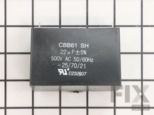
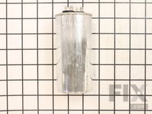
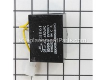
Capacitor
The capacitor has two functions; it induces voltage into the rotor as well as regulates voltage. A bad capacity will result in a low voltage reading from the generator as the power being generated will be from the residual magnetism of the rotor (usually about 2-5V). To test a capacitor, a multi-meter that can test capacitance is required. To test a capacitor, it must first be removed from the generator and discharged. Be careful when removing the wire leads that a short is not created across the capacitors terminals. To discharge, use a screwdriver with an insulated handle to cross the terminals on the capacitor (this will result in a loud pop and a spark). Once discharged, take a reading from the capacitor. The measured capacitance should be +/-5uf of the specified rating printed on the side of the capacitor. If not, the capacitor should be replaced.
Alternator
The alternator uses residual magnetism from the windings to charge the capacitor. If the generator has not been used for an extended period the magnetism can be lost and the capacitor will not be charged. If this occurs the capacitor must be ‘field flashed’ to restore its charge so the rotor can once again be excited. To charge the capacitor a special charging harness must be constructed consisting of a short length of 12-gauge wire with a standard 120v plug on one end. The opposite end should have a few female blade connectors which will be attached to the terminals on the capacitor. A single pole momentary switch is added to the live or positive side of the wiring harness. Connect the harness to the capacitors terminals and plug in the plug end to a 120v outlet. The momentary switch should be depressed for not more than one second. This will restore the capacitors charge. It can then be reinstalled in the generator. Once the capacitor is charged, care must be taken to ensure that no shorts are created between the terminals while it is reinstalled. Again, if there is any doubt or confusion about this process, take the generator to a professional to have this repair performed.
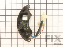
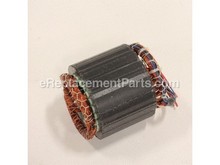
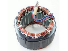
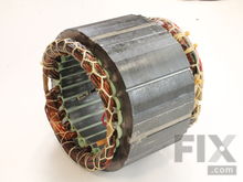
Stator
There are two types of stators used in generators; brushed and brushless. The stator is typically made up of three windings; two power windings and one winding that is used to either excite the rotor on a brushed stator or charge the capacitor on a brushless stator. The magnetically charged rotor rotates inside of the fixed stator windings, which produces electricity. To test a brushless stator, the wires from the stator to the electrical panel will first need to be removed. You will also need some information from the manufacturer; the function of each of the stator wires, as well as the normal resistance reading for each of the coils within the stator. Once this information is found, you can begin testing. The first test will determine if there is an open circuit within the winding, which would indicate a damaged or broken winding. Using a multi-meter set to test resistance, connect the multi-meter to each end of the wire coil using the leads. The meter should give a resistance measurement that is within the manufacturers specifications. A reading outside of this spec will indicate a bad winding. Perform this test on both power windings. The next test will check for a short between the windings and ground. The manufacturer will specify which stator lead to use for this test. Set the multi-meter to test resistance. One test lead will be connected to the stator lead specified by the manufacturer, and the other lead will be connected to a clean frame ground on the generator. The meter should read “OL” (overload) or Infinity. If a resistance measurement is detected, there is likely a short to ground condition in the stator. The final test for a brushless stator is to test for a short between windings. Again, the manufacturer will need to specify which leads to use for this test. Set your multi-meter to test resistance. The test leads will be connected to two of the stator leads specified by the manufacturer. The two leads will be one lead from each of the power windings. The meter should read “OL” (overload) or Infinity. If a resistance measurement is detected that would indicate a short between the windings in the stator. To test a brushed stator: Isolate the stator by removing the connections to the AVR (automatic voltage regulator) as well as the wires running from the stator to the electrical panel. Set your multi-meter to test resistance. One of the test leads should be connected to a clean frame ground, and the other used to test each of the leads from the stator. Each lead should read “OL” (overload) or Infinity. If any of the leads give a resistance measurement that would indicate a short to ground and a bad Stator.
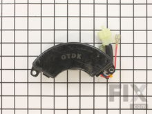
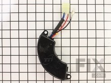
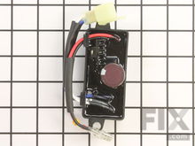
Automatic Voltage Regulator
The AVR is a circuit that regulates and balances the amount of voltage being output from the generator. All AVRs will have an adjustment screw which allows for the fine-tuning of the voltage output. Diagnosing a faulty AVR is done by a process of elimination; Start by testing the generators main circuit breaker. If the breaker tests good for continuity, next test the wiring within the electrical panel and from the breaker to the stator. If the wiring tests good, try adjusting the AVR to make sure it is not out of adjustment. If there is no change in output then check the rotor brushes to make sure they are in good condition and are making contact with the rotor. If everything tests good up until this point, test the stator itself. If the stator is producing power then the AVR is faulty and will need to be replaced.
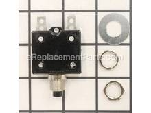
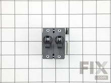
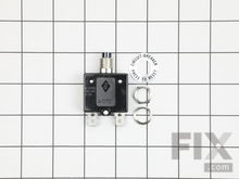
Circuit Breaker
If your generator engine is running but is producing no or low output, the circuit breaker is the first thing you should check. The breaker is a safety feature designed to automatically switch off if a surge of electricity or overload is detected. A surge can be caused by using a device that draws more power than the breaker is rated for, using multiple ‘heavy load’ devices at the same time, or if a short occurs within the circuit. Some breakers will have colored indicators to show if they have been tripped, but some will not give any indication at all. Cycle the breaker off and on and try the outlet again. If the outlet is still not working, confirm that the breaker is set to the on position and use a multi-meter to measure resistance on the lead wire connections on the inside of the electrical panel. If any resistance is read, than the breaker is good. If the meter reads ‘OL’ (overload) or Infinity, the breaker is bad and should be replaced.
More Repair Parts
Still not sure which part is broken? We can offer you custom troubleshooting help if you search with your model number.